QuickStart
CadQueryで何ができるのか、ちょっと見てみたいですか? このクイックスタートでは、簡単な例を使ってCadQueryの基本を説明します。
Prerequisites: CadQuery and CQ-editor installation
If you have not already done so, follow the CadQueryのインストール, to install CadQuery and CQ-editor.
インストール後、CQ-editorを起動します。
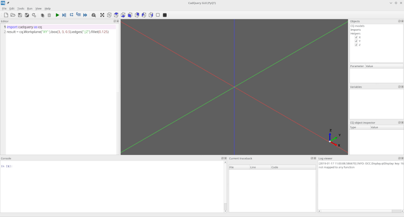
左側にあるCadQueryのコードエディタを探します。 簡単なブロックのスクリプトから始めることがわかります。
私たちが達成すること
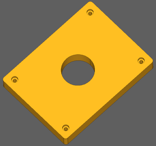
このクイックスタートでは、完全パラメトリックベアリングのピローブロックを作成します。 完成したオブジェクトは次のようになります。
私たちのブロックには、以下のような機能を持たせたいと考えています:
ブロックの中央に608 ( 'skate' ) ベアリングが1個入る大きさでなければなりません。
角にはM2ソケットヘッド・キャップ・スクリュー用のザグリ穴があるはずです。
ブロックの長さと幅は、ユーザーが合理的なサイズに設定できることが望ましいです。
人間ならこう表現します:
"80mm×60mm×10mmの長方形のブロックの角にはM2ソケットヘッドキャップスクリュー用のザグリ穴があり、中央にはベアリング用の直径22mmの円形ポケットがあります。"
人間の説明文はとてもエレガントでしょう?私たちの完成したスクリプトが、この人間向けの説明よりもあまり複雑なものにならないことを願っています。
さて、どうするかな。
シンプルな1枚のプレートから始める
Let's start with a simple model that makes nothing but a rectangular block, but with place-holders for the dimensions. Paste this into the code editor:
1height = 60.0
2width = 80.0
3thickness = 10.0
4
5# make the base
6result = cq.Workplane("XY").box(height, width, thickness)
7
8# Render the solid
9show_object(result)
ツールバーの緑色のレンダリングボタンを押して、スクリプトを実行します。ベースオブジェクトが表示されるはずです。
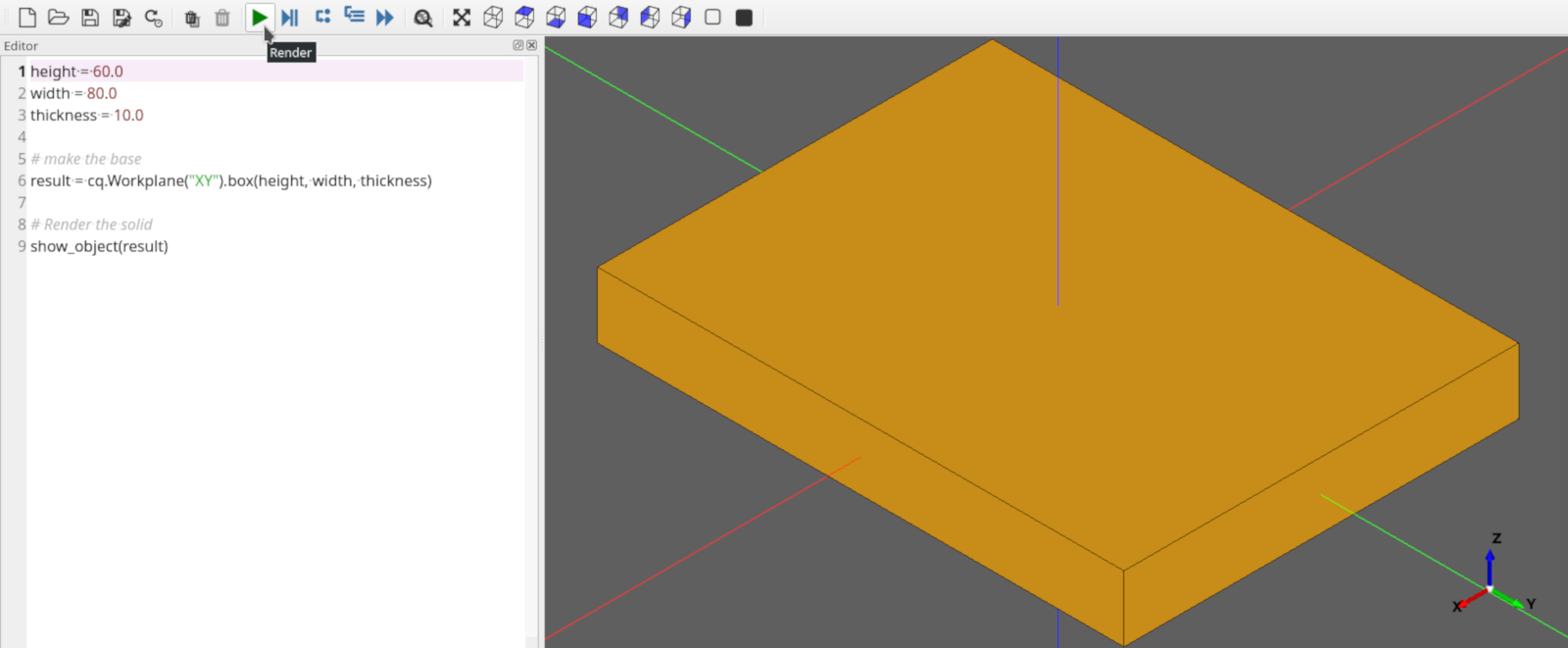
Nothing special, but its a start!
穴を追加する
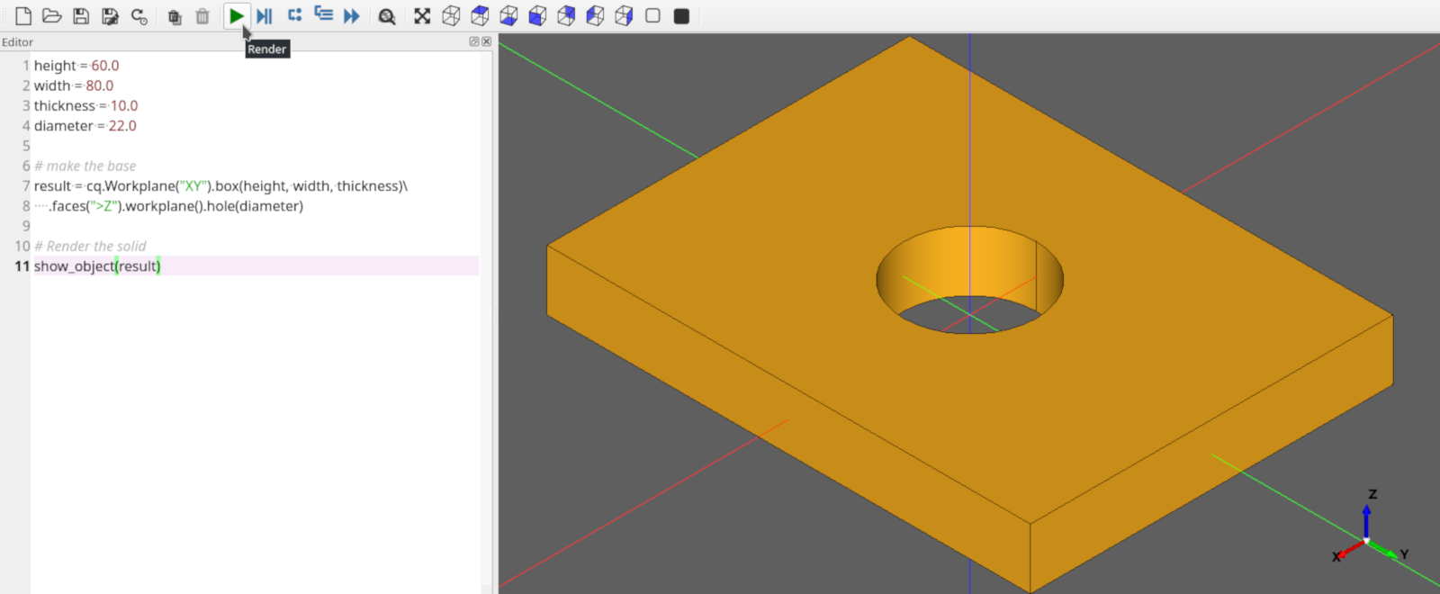
Our pillow block needs to have a 22mm diameter hole in the center to hold the bearing.
This modification will do the trick:
 1height = 60.0
 2width = 80.0
 3thickness = 10.0
 4diameter = 22.0
 5
 6# make the base
 7result = (
 8    cq.Workplane("XY")
 9    .box(height, width, thickness)
10    .faces(">Z")
11    .workplane()
12    .hole(diameter)
13)
14
15# Render the solid
16show_object(result)
Rebuild your model by clicking the Render button. Your block should look like this:
The code is pretty compact, let's step through it.
Line 4 adds a new parameter, diameter, for the diameter of the hole
Lines 10-12, we're adding the hole.
cadquery.Workplane.faces() selects the top-most face in the Z direction, and then
cadquery.Workplane.workplane() begins a new workplane located on this face. The center of this workplane
is located at the center of mass of the shape, which in this case is the center of the plate.
Finally, cadquery.Workplane.hole() drills a hole through the part, 22mm in diameter.
注釈
Don't worry about the CadQuery syntax now.. you can learn all about it in the API Reference later.
More Holes
Ok, that hole was not too hard, but what about the counter-bored holes in the corners?
An M2 Socket head cap screw has these dimensions:
Head Diameter : 3.8 mm
Head height : 2.0 mm
Clearance Hole : 2.4 mm
CounterBore diameter : 4.4 mm
The centers of these holes should be 6mm from the edges of the block. And, we want the block to work correctly even when the block is re-sized by the user.
Don't tell me we'll have to repeat the steps above 8 times to get counter-bored holes? Good news!-- we can get the job done with just a few lines of code. Here's the code we need:
 1height = 60.0
 2width = 80.0
 3thickness = 10.0
 4diameter = 22.0
 5padding = 12.0
 6
 7# make the base
 8result = (
 9    cq.Workplane("XY")
10    .box(height, width, thickness)
11    .faces(">Z")
12    .workplane()
13    .hole(diameter)
14    .faces(">Z")
15    .workplane()
16    .rect(height - padding, width - padding, forConstruction=True)
17    .vertices()
18    .cboreHole(2.4, 4.4, 2.1)
19)
20# Render the solid
21show_object(result)
After clicking the Render button to re-execute the model, you should see something like this:
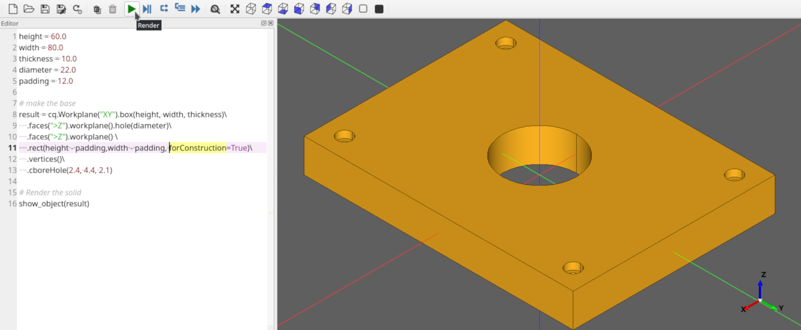
There is quite a bit going on here, so let's break it down a bit.
5行目 は、プレートの端から穴までの距離を決める新しいパディングパラメーターを作成します。
Lines 14-15 selects the top-most face of the block, and creates a workplane on the top of that face, which we'll use to define the centers of the holes in the corners.
Line 16 draws a rectangle 12mm smaller than the overall length and width of the block, which we will use to locate the corner holes. We'll use the vertices ( corners ) of this rectangle to locate the holes. The rectangle's center is at the center of the workplane, which in this case coincides with the center of the bearing hole.
There are a couple of things to note about this line:
The
cadquery.Workplane.rect()function draws a rectangle. forConstruction=True tells CadQuery that this rectangle will not form a part of the solid, but we are just using it to help define some other geometry.Unless you specify otherwise, a rectangle is drawn with its center on the current workplane center-- in this case, the center of the top face of the block. So this rectangle will be centered on the face.
Line 17 selects the vertices of the rectangle, which we will use for the centers of the holes.
The cadquery.Workplane.vertices() function selects the corners of the rectangle.
Line 18 uses the cboreHole function to draw the holes.
The cadquery.Workplane.cboreHole() function is a handy CadQuery function that makes a counterbored hole.
Like most other CadQuery functions, it operates on the values on the stack. In this case, since we
selected the four vertices before calling the function, the function operates on each of the four points--
which results in a counterbore hole at each of the rectangle corners.
Filleting
Almost done. Let's just round the corners of the block a bit. That's easy, we just need to select the edges and then fillet them:
We can do that using the preset dictionaries in the parameter definition:
 1height = 60.0
 2width = 80.0
 3thickness = 10.0
 4diameter = 22.0
 5padding = 12.0
 6
 7# make the base
 8result = (
 9    cq.Workplane("XY")
10    .box(height, width, thickness)
11    .faces(">Z")
12    .workplane()
13    .hole(diameter)
14    .faces(">Z")
15    .workplane()
16    .rect(height - padding, width - padding, forConstruction=True)
17    .vertices()
18    .cboreHole(2.4, 4.4, 2.1)
19    .edges("|Z")
20    .fillet(2.0)
21)
22
23# Render the solid
24show_object(result)
Line 19 To grab the right edges, the cadquery.Workplane.edges() selects all of the
edges that are parallel to the Z axis ("|Z").
Line 20 fillets the edges using the cadquery.Workplane.fillet() method.
The finished product looks like this:

Exporting
If you want to fabricate a physical object you need to export the result to STL or DXF. Additionally, exporting as STEP for post-processing in another CAD tool is also possible.
This can be easily accomplished using the cadquery.exporters.export() function:
 1height = 60.0
 2width = 80.0
 3thickness = 10.0
 4diameter = 22.0
 5padding = 12.0
 6
 7# make the base
 8result = (
 9    cq.Workplane("XY")
10    .box(height, width, thickness)
11    .faces(">Z")
12    .workplane()
13    .hole(diameter)
14    .faces(">Z")
15    .workplane()
16    .rect(height - padding, width - padding, forConstruction=True)
17    .vertices()
18    .cboreHole(2.4, 4.4, 2.1)
19    .edges("|Z")
20    .fillet(2.0)
21)
22
23# Render the solid
24show_object(result)
25
26# Export
27cq.exporters.export(result, "result.stl")
28cq.exporters.export(result.section(), "result.dxf")
29cq.exporters.export(result, "result.step")
Done!
You just made a parametric, model that can generate pretty much any bearing pillow block with <30 lines of code.
Want to learn more?
The Examples contains lots of examples demonstrating cadquery features
The API Reference is a good overview of language features grouped by function
The CadQueryクラスの概要 is the hard-core listing of all functions available.