アセンブリ
Assembly tutorial
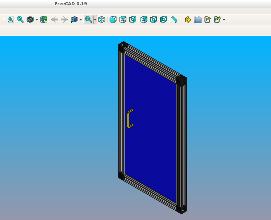
このセクションの目的は、アセンブリーと拘束の機能を使用して現実的なモデルを作成する方法を示すことです。20x20Vスロットプロファイルで構成されたエンクロージャドアアセンブリです。
パラメータを定義する
後で簡単に寸法を変更できるように、モデルパラメータの定義から始めます。
import cadquery as cq

# Parameters
H = 400
W = 200
D = 350

PROFILE = cq.importers.importDXF("vslot-2020_1.dxf").wires()

SLOT_D = 5
PANEL_T = 3

HANDLE_D = 20
HANDLE_L = 50
HANDLE_W = 4
VスロットプロファイルがDXFファイルからインポートされていることに注目してください。このようにして、ItemやBoschのような他のアルミニウム押し出しタイプに変更することは非常に容易です。ベンダーは通常、DXFファイルを提供しています。
再利用可能なコンポーネントの定義
次に、指定したパラメータに基づいてアセンブリ構成部品を生成する関数を定義します。
def make_vslot(l):
    return PROFILE.toPending().extrude(l)


def make_connector():
    rv = (
        cq.Workplane()
        .box(20, 20, 20)
        .faces("<X")
        .workplane()
        .cboreHole(6, 15, 18)
        .faces("<Z")
        .workplane(centerOption="CenterOfMass")
        .cboreHole(6, 15, 18)
    )

    # tag mating faces
    rv.faces(">X").tag("X").end()
    rv.faces(">Z").tag("Z").end()

    return rv


def make_panel(w, h, t, cutout):
    rv = (
        cq.Workplane("XZ")
        .rect(w, h)
        .extrude(t)
        .faces(">Y")
        .vertices()
        .rect(2 * cutout, 2 * cutout)
        .cutThruAll()
        .faces("<Y")
        .workplane()
        .pushPoints([(-w / 3, HANDLE_L / 2), (-w / 3, -HANDLE_L / 2)])
        .hole(3)
    )

    # tag mating edges
    rv.faces(">Y").edges("%CIRCLE").edges(">Z").tag("hole1")
    rv.faces(">Y").edges("%CIRCLE").edges("<Z").tag("hole2")

    return rv


def make_handle(w, h, r):
    pts = ((0, 0), (w, 0), (w, h), (0, h))

    path = cq.Workplane().polyline(pts)

    rv = (
        cq.Workplane("YZ")
        .rect(r, r)
        .sweep(path, transition="round")
        .tag("solid")
        .faces("<X")
        .workplane()
        .faces("<X", tag="solid")
        .hole(r / 1.5)
    )

    # tag mating faces
    rv.faces("<X").faces(">Y").tag("mate1")
    rv.faces("<X").faces("<Y").tag("mate2")

    return rv
初期アセンブリ
次に、すべての構成要素をインスタンス化し、アセンブリーに追加します。
# define the elements
door = (
    cq.Assembly()
    .add(make_vslot(H), name="left")
    .add(make_vslot(H), name="right")
    .add(make_vslot(W), name="top")
    .add(make_vslot(W), name="bottom")
    .add(make_connector(), name="con_tl", color=cq.Color("black"))
    .add(make_connector(), name="con_tr", color=cq.Color("black"))
    .add(make_connector(), name="con_bl", color=cq.Color("black"))
    .add(make_connector(), name="con_br", color=cq.Color("black"))
    .add(
        make_panel(W + SLOT_D, H + SLOT_D, PANEL_T, SLOT_D),
        name="panel",
        color=cq.Color(0, 0, 1, 0.2),
    )
    .add(
        make_handle(HANDLE_D, HANDLE_L, HANDLE_W),
        name="handle",
        color=cq.Color("yellow"),
    )
)
拘束の定義
次に、すべての制約を定義します。
# define the constraints
(
    door
    # left profile
    .constrain("left@faces@<Z", "con_bl?Z", "Plane")
    .constrain("left@faces@<X", "con_bl?X", "Axis")
    .constrain("left@faces@>Z", "con_tl?Z", "Plane")
    .constrain("left@faces@<X", "con_tl?X", "Axis")
    # top
    .constrain("top@faces@<Z", "con_tl?X", "Plane")
    .constrain("top@faces@<Y", "con_tl@faces@>Y", "Axis")
    # bottom
    .constrain("bottom@faces@<Y", "con_bl@faces@>Y", "Axis")
    .constrain("bottom@faces@>Z", "con_bl?X", "Plane")
    # right connectors
    .constrain("top@faces@>Z", "con_tr@faces@>X", "Plane")
    .constrain("bottom@faces@<Z", "con_br@faces@>X", "Plane")
    .constrain("left@faces@>Z", "con_tr?Z", "Axis")
    .constrain("left@faces@<Z", "con_br?Z", "Axis")
    # right profile
    .constrain("right@faces@>Z", "con_tr@faces@>Z", "Plane")
    .constrain("right@faces@<X", "left@faces@<X", "Axis")
    # panel
    .constrain("left@faces@>X[-4]", "panel@faces@<X", "Plane")
    .constrain("left@faces@>Z", "panel@faces@>Z", "Axis")
    # handle
    .constrain("panel?hole1", "handle?mate1", "Plane")
    .constrain("panel?hole2", "handle?mate2", "Point")
)
Should you need to do something unusual that is not possible with the string
based selectors (e.g. use cadquery.selectors.BoxSelector or a user-defined selector class),
it is possible to pass cadquery.Shape objects to the cadquery.Assembly.constrain() method directly. For example, the above
.constrain("part1@faces@>Z", "part3@faces@<Z", "Axis")
is equivalent to
.constrain("part1", part1.faces(">z").val(), "part3", part3.faces("<Z").val(), "Axis")
This method requires a cadquery.Shape object, so remember to use the cadquery.Workplane.val()
method to pass a single cadquery.Shape and not the whole cadquery.Workplane object.
Final result
Below is the complete code including the final solve step.
import cadquery as cq

# Parameters
H = 400
W = 200
D = 350

PROFILE = cq.importers.importDXF("vslot-2020_1.dxf").wires()

SLOT_D = 6
PANEL_T = 3

HANDLE_D = 20
HANDLE_L = 50
HANDLE_W = 4


def make_vslot(l):
    return PROFILE.toPending().extrude(l)


def make_connector():
    rv = (
        cq.Workplane()
        .box(20, 20, 20)
        .faces("<X")
        .workplane()
        .cboreHole(6, 15, 18)
        .faces("<Z")
        .workplane(centerOption="CenterOfMass")
        .cboreHole(6, 15, 18)
    )

    # tag mating faces
    rv.faces(">X").tag("X").end()
    rv.faces(">Z").tag("Z").end()

    return rv


def make_panel(w, h, t, cutout):
    rv = (
        cq.Workplane("XZ")
        .rect(w, h)
        .extrude(t)
        .faces(">Y")
        .vertices()
        .rect(2 * cutout, 2 * cutout)
        .cutThruAll()
        .faces("<Y")
        .workplane()
        .pushPoints([(-w / 3, HANDLE_L / 2), (-w / 3, -HANDLE_L / 2)])
        .hole(3)
    )

    # tag mating edges
    rv.faces(">Y").edges("%CIRCLE").edges(">Z").tag("hole1")
    rv.faces(">Y").edges("%CIRCLE").edges("<Z").tag("hole2")

    return rv


def make_handle(w, h, r):
    pts = ((0, 0), (w, 0), (w, h), (0, h))

    path = cq.Workplane().polyline(pts)

    rv = (
        cq.Workplane("YZ")
        .rect(r, r)
        .sweep(path, transition="round")
        .tag("solid")
        .faces("<X")
        .workplane()
        .faces("<X", tag="solid")
        .hole(r / 1.5)
    )

    # tag mating faces
    rv.faces("<X").faces(">Y").tag("mate1")
    rv.faces("<X").faces("<Y").tag("mate2")

    return rv


# define the elements
door = (
    cq.Assembly()
    .add(make_vslot(H), name="left")
    .add(make_vslot(H), name="right")
    .add(make_vslot(W), name="top")
    .add(make_vslot(W), name="bottom")
    .add(make_connector(), name="con_tl", color=cq.Color("black"))
    .add(make_connector(), name="con_tr", color=cq.Color("black"))
    .add(make_connector(), name="con_bl", color=cq.Color("black"))
    .add(make_connector(), name="con_br", color=cq.Color("black"))
    .add(
        make_panel(W + 2 * SLOT_D, H + 2 * SLOT_D, PANEL_T, SLOT_D),
        name="panel",
        color=cq.Color(0, 0, 1, 0.2),
    )
    .add(
        make_handle(HANDLE_D, HANDLE_L, HANDLE_W),
        name="handle",
        color=cq.Color("yellow"),
    )
)

# define the constraints
(
    door
    # left profile
    .constrain("left@faces@<Z", "con_bl?Z", "Plane")
    .constrain("left@faces@<X", "con_bl?X", "Axis")
    .constrain("left@faces@>Z", "con_tl?Z", "Plane")
    .constrain("left@faces@<X", "con_tl?X", "Axis")
    # top
    .constrain("top@faces@<Z", "con_tl?X", "Plane")
    .constrain("top@faces@<Y", "con_tl@faces@>Y", "Axis")
    # bottom
    .constrain("bottom@faces@<Y", "con_bl@faces@>Y", "Axis")
    .constrain("bottom@faces@>Z", "con_bl?X", "Plane")
    # right connectors
    .constrain("top@faces@>Z", "con_tr@faces@>X", "Plane")
    .constrain("bottom@faces@<Z", "con_br@faces@>X", "Plane")
    .constrain("left@faces@>Z", "con_tr?Z", "Axis")
    .constrain("left@faces@<Z", "con_br?Z", "Axis")
    # right profile
    .constrain("right@faces@>Z", "con_tr@faces@>Z", "Plane")
    .constrain("right@faces@<X", "left@faces@<X", "Axis")
    # panel
    .constrain("left@faces@>X[-4]", "panel@faces@<X", "Plane")
    .constrain("left@faces@>Z", "panel@faces@>Z", "Axis")
    # handle
    .constrain("panel?hole1", "handle?mate1", "Plane")
    .constrain("panel?hole2", "handle?mate2", "Point")
)

# solve
door.solve()

show_object(door, name="door")
Data export
The resulting assembly can be exported as a STEP file or in a internal OCCT XML format.
STEP can be loaded in all CAD tool, e.g. in FreeCAD and the XML be used in other applications using OCCT.
1door.export("door.step")
2door.export("door.xml")
Object locations
Objects can be added to an assembly with initial locations supplied, such as:
import cadquery as cq

cone = cq.Solid.makeCone(1, 0, 2)

assy = cq.Assembly()
assy.add(
    cone,
    loc=cq.Location((0, 0, 0), (1, 0, 0), 180),
    name="cone0",
    color=cq.Color("green"),
)
assy.add(cone, name="cone1", color=cq.Color("blue"))

show_object(assy)
As an alternative to the user calculating locations, constraints and the method
solve() can be used to position objects in an assembly.
If initial locations and the method solve() are used the solver will
overwrite these initial locations with it's solution, however initial locations can still affect the
final solution. In an underconstrained system the solver may not move an object if it does not
contribute to the cost function, or if multiple solutions exist (ie. multiple instances
where the cost function is at a minimum) initial locations can cause the solver to converge on one
particular solution. For very complicated assemblies setting approximately correct initial locations
can also reduce the computational time required.
Constraints
Constraints are often a better representation of the real world relationship the user wants to
model than directly supplying locations. In the above example the real world relationship is that
the bottom face of each cone should touch, which can be modelled with a Plane constraint. When the
user provides explicit locations (instead of constraints) then they are also responsible for updating
them when, for example, the location of cone1 changes.
When at least one constraint is supplied and the method solve() is run, an
optimization problem is set up. Each constraint provides a cost function that depends on the
position and orientation (represented by a Location) of the two objects specified
when creating the constraint. The solver varies the location of the assembly's children and attempts
to minimize the sum of all cost functions. Hence by reading the formulae of the cost functions
below, you can understand exactly what each constraint does.
Point
The Point constraint is a frequently used constraint that minimizes the distance between two points. Some example uses are centering faces or aligning verticies, but it is also useful with dummy vertices to create offsets between two parts.
The cost function is:
Where:
\(param\) is the parameter of the constraint, which defaults to 0,
\(\vec{ c_i }\) is the center of the ith object, and
\(\lvert \vec{ v } \rvert\) is the modulus of \(\vec{ v }\), ie. the length of \(\vec{ v }\).
When creating a Point constraint, the param argument can be used to specify a desired offset
between the two centers. This offset does not have a direction associated with it, if you want to
specify an offset in a specific direction then you should use a dummy Vertex.
The Point constraint uses the Center() to find the center of the
argument. Hence it will work with all subclasses of Shape.
import cadquery as cq

# Use the Point constraint to position boxes relative to an arc
line = cq.Edge.makeCircle(radius=10, angle1=0, angle2=90)
box = cq.Workplane().box(1, 1, 1)

assy = cq.Assembly()
assy.add(line, name="line")

# position the red box on the center of the arc
assy.add(box, name="box0", color=cq.Color("red"))
assy.constrain("line", "box0", "Point")

# position the green box at a normalized distance of 0.8 along the arc
position0 = line.positionAt(0.8)
assy.add(box, name="box1", color=cq.Color("green"))
assy.constrain(
    "line",
    cq.Vertex.makeVertex(*position0.toTuple()),
    "box1",
    box.val(),
    "Point",
)

# position the orange box 2 units in any direction from the green box
assy.add(box, name="box2", color=cq.Color("orange"))
assy.constrain(
    "line",
    cq.Vertex.makeVertex(*position0.toTuple()),
    "box2",
    box.val(),
    "Point",
    param=2,
)

# position the blue box offset 2 units in the x direction from the green box
position1 = position0 + cq.Vector(2, 0, 0)
assy.add(box, name="box3", color=cq.Color("blue"))
assy.constrain(
    "line",
    cq.Vertex.makeVertex(*position1.toTuple()),
    "box3",
    box.val(),
    "Point",
)

assy.solve()
show_object(assy)
Axis
The Axis constraint minimizes the angle between two vectors. It is frequently used to align faces and control the rotation of an object.
The cost function is:
Where:
\(k_{ dir }\) is a scaling factor for directional constraints,
\(param\) is the parameter of the constraint, which defaults to 180 degrees,
\(\vec{d_i}\) is the direction created from the ith object argument as described below, and
\(\vec{ d_1 } \angle \vec{ d_2 }\) is the angle between \(\vec{ d_1 }\) and \(\vec{ d_2 }\).
The argument param defaults to 180 degrees, which sets the two directions opposite
to each other. This represents what is often called a "mate" relationship, where the external faces
of two objects touch.
import cadquery as cq

cone = cq.Solid.makeCone(1, 0, 2)

assy = cq.Assembly()
assy.add(cone, name="cone0", color=cq.Color("green"))
assy.add(cone, name="cone1", color=cq.Color("blue"))
assy.constrain("cone0@faces@<Z", "cone1@faces@<Z", "Axis")

assy.solve()
show_object(assy)
If the param argument is set to zero, then the two objects will point in the same direction.
This is often used when one object goes through another, such as a pin going into a hole in a plate:
import cadquery as cq

plate = cq.Workplane().box(10, 10, 1).faces(">Z").workplane().hole(2)
cone = cq.Solid.makeCone(0.8, 0, 4)

assy = cq.Assembly()
assy.add(plate, name="plate", color=cq.Color("green"))
assy.add(cone, name="cone", color=cq.Color("blue"))
# place the center of the flat face of the cone in the center of the upper face of the plate
assy.constrain("plate@faces@>Z", "cone@faces@<Z", "Point")

# set both the flat face of the cone and the upper face of the plate to point in the same direction
assy.constrain("plate@faces@>Z", "cone@faces@<Z", "Axis", param=0)

assy.solve()
show_object(assy)
In creating an Axis constraint, a direction vector is extracted in one of three different ways, depending on the object's type.
Face:Using
normalAt()EdgeandgeomType()is"CIRCLE":Using
normal()EdgeandgeomType()is not"CIRCLE":Using
tangentAt()
Using any other type of object will raise a ValueError. By far the most common use case
is to define an Axis constraint from a Face.
import cadquery as cq
from math import cos, sin, pi

# Create a sinusoidal surface:
surf = cq.Workplane().parametricSurface(
    lambda u, v: (u, v, 5 * sin(pi * u / 10) * cos(pi * v / 10)),
    N=40,
    start=0,
    stop=20,
)

# Create a cone with a small, flat tip:
cone = (
    cq.Workplane()
    .add(cq.Solid.makeCone(1, 0.1, 2))
    # tag the tip for easy reference in the constraint:
    .faces(">Z")
    .tag("tip")
    .end()
)

assy = cq.Assembly()
assy.add(surf, name="surf", color=cq.Color("lightgray"))
assy.add(cone, name="cone", color=cq.Color("green"))
# set the Face on the tip of the cone to point in
# the opposite direction of the center of the surface:
assy.constrain("surf", "cone?tip", "Axis")
# to make the example clearer, move the cone to the center of the face:
assy.constrain("surf", "cone?tip", "Point")
assy.solve()

show_object(assy)
Plane
The Plane constraint is simply a combination of both the Point and Axis constraints. It is a convenient shortcut for a commonly used combination of constraints. It can be used to shorten the previous example from the two constraints to just one:
assy = cq.Assembly()
assy.add(surf, name="surf", color=cq.Color("lightgray"))
assy.add(cone, name="cone", color=cq.Color("green"))
-# set the Face on the tip of the cone to point in
-# the opposite direction of the center of the surface:
-assy.constrain("surf", "cone?tip", "Axis")
-# to make the example clearer, move the cone to the center of the face:
-assy.constrain("surf", "cone?tip", "Point")
+assy.constrain("surf", "cone?tip", "Plane")
assy.solve()

show_object(assy)
The result of this code is identical to the above two constraint example.
For the cost function of Plane, please see the Point and Axis sections. The param argument is applied to Axis and should be left as the default value for a "mate" style
constraint (two surfaces touching) or can be set to 0 for a through surface constraint (see
description in the Axis constraint section).
PointInPlane
PointInPlane positions the center of the first object within the plane defined by the second object. The cost function is:
Where:
\(\vec{ c }\) is the center of the first argument,
\(p_\text{ offset }\) is a plane created from the second object, offset in the plane's normal direction by
param, and\(\operatorname{dist}( \vec{ a }, b)\) is the distance between point \(\vec{ a }\) and plane \(b\).
import cadquery as cq

# Create an L-shaped object:
bracket = (
    cq.Workplane("YZ")
    .hLine(1)
    .vLine(0.1)
    .hLineTo(0.2)
    .vLineTo(1)
    .hLineTo(0)
    .close()
    .extrude(1)
    # tag some faces for easy reference:
    .faces(">Y[1]")
    .tag("inner_vert")
    .end()
    .faces(">Z[1]")
    .tag("inner_horiz")
    .end()
)

box = cq.Workplane().box(0.5, 0.5, 0.5)

assy = cq.Assembly()
assy.add(bracket, name="bracket", color=cq.Color("gray"))
assy.add(box, name="box", color=cq.Color("green"))

# lock bracket orientation:
assy.constrain("bracket@faces@>Z", "box@faces@>Z", "Axis", param=0)
assy.constrain("bracket@faces@>X", "box@faces@>X", "Axis", param=0)

# constrain the bottom of the box to be on the plane defined by inner_horiz:
assy.constrain("box@faces@<Z", "bracket?inner_horiz", "PointInPlane")
# constrain the side of the box to be 0.2 units from the plane defined by inner_vert
assy.constrain("box@faces@<Y", "bracket?inner_vert", "PointInPlane", param=0.2)
# constrain the end of the box to be 0.1 units inside the end of the bracket
assy.constrain("box@faces@>X", "bracket@faces@>X", "PointInPlane", param=-0.1)

assy.solve()
show_object(assy)
PointOnLine
PointOnLine positions the center of the first object on the line defined by the second object. The cost function is:
Where:
\(\vec{ c }\) is the center of the first argument,
\(l\) is a line created from the second object
\(param\) is the parameter of the constraint, which defaults to 0,
\(\operatorname{dist}( \vec{ a }, b)\) is the distance between point \(\vec{ a }\) and line \(b\).
import cadquery as cq

b1 = cq.Workplane().box(1, 1, 1)
b2 = cq.Workplane().sphere(0.15)

assy = (
    cq.Assembly()
    .add(b1, name="b1")
    .add(b2, loc=cq.Location((0, 0, 4)), name="b2", color=cq.Color("red"))
)

# fix the position of b1
assy.constrain("b1", "Fixed")
# b2 on one of the edges of b1
assy.constrain("b2", "b1@edges@>>Z and >>Y", "PointOnLine")
# b2 on another of the edges of b1
assy.constrain("b2", "b1@edges@>>Z and >>X", "PointOnLine")
# effectively b2 will be constrained to be on the intersection of the two edges

assy.solve()
show_object(assy)
FixedPoint
FixedPoint fixes the position of the given argument to be equal to the given point specified via the parameter of the constraint. This constraint locks all translational degrees of freedom of the argument. The cost function is:
Where:
\(\vec{ c }\) is the center of the argument,
\(param\) is the parameter of the constraint - tuple specifying the target position.
import cadquery as cq

b1 = cq.Workplane().box(1, 1, 1)
b2 = cq.Workplane().sphere(0.15)

assy = (
    cq.Assembly()
    .add(b1, name="b1")
    .add(b2, loc=cq.Location((0, 0, 4)), name="b2", color=cq.Color("red"))
    .add(b1, loc=cq.Location((-2, 0, 0)), name="b3", color=cq.Color("red"))
)

pnt = (0.5, 0.5, 0.5)

# fix the position of b1
assy.constrain("b1", "Fixed")
# fix b2 center at point
assy.constrain("b2", "FixedPoint", pnt)
# fix b3 vertex position at point
assy.constrain("b3@vertices@<X and <Y and <Z", "FixedPoint", pnt)

assy.solve()
show_object(assy)
FixedRotation
FixedRotation fixes the rotation of the given argument to be equal to the value specified via the parameter of the constraint.
This constraint locks all rotational degrees of freedom of the argument. The cost function is:
Where:
\(\vec{ R }\) vector of the rotation angles of the rotation applied to the argument,
\(param\) is the parameter of the constraint - tuple specifying the target rotation.
import cadquery as cq

b1 = cq.Workplane().box(1, 1, 1)
b2 = cq.Workplane().rect(0.1, 0.1).extrude(1, taper=-15)

assy = (
    cq.Assembly()
    .add(b1, name="b1")
    .add(b2, loc=cq.Location((0, 0, 4)), name="b2", color=cq.Color("red"))
)

# fix the position of b1
assy.constrain("b1", "Fixed")
# fix b2 bottom face position (but not rotation)
assy.constrain("b2@faces@<Z", "FixedPoint", (0, 0, 0.5))
# fix b2 rotational degrees of freedom too
assy.constrain("b2", "FixedRotation", (45, 0, 45))

assy.solve()
show_object(assy)
FixedAxis
FixedAxis fixes the orientation of the given argument's normal or tangent to be equal to the orientation of the vector specified via the parameter of the constraint. This constraint locks two rotational degrees of freedom of the argument. The cost function is:
Where:
\(\vec{ a }\) normal or tangent vector of the argument,
\(param\) is the parameter of the constraint - tuple specifying the target direction.
import cadquery as cq

b1 = cq.Workplane().box(1, 1, 1)
b2 = cq.Workplane().rect(0.1, 0.1).extrude(1, taper=-15)

assy = (
    cq.Assembly()
    .add(b1, name="b1")
    .add(b2, loc=cq.Location((0, 0, 4)), name="b2", color=cq.Color("red"))
)

# fix the position of b1
assy.constrain("b1", "Fixed")
# fix b2 bottom face position (but not rotation)
assy.constrain("b2@faces@<Z", "FixedPoint", (0, 0, 0.5))
# fix b2 some rotational degrees of freedom too
assy.constrain("b2@faces@>Z", "FixedAxis", (1, 0, 2))

assy.solve()
show_object(assy)
Assembly colors
Aside from RGBA values, the Color class can be instantiated from a text name. Valid names are
listed along with a color sample below: